Rotating Shifts:
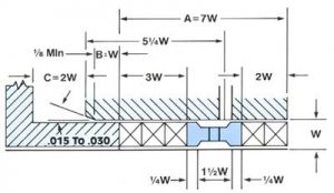
Dimension A shown on this drawing is the total depth of packing including lantern gland. A standard depth of 7W or 7 times the packing space has been established when a lantern gland is used. A depth dimension of 5W is used where lantern gland is omitted.

| English | Metric | ||
| Shaft Range | W | Shaft Range | W |
| 5/8″ to and including 1-1/8″ shaft | 5/16″ | 16mm to and including 29mm shaft | 8mm |
| 1-1/8″ to and including 1-7/8″ shaft | 3/8″ | 29mm to and including 48mm shaft | 10mm |
| 1-7/8″ to and including 3″ shaft | 1/2″ | 48mm to and including 75mm shaft | 13mm |
| 3″ to and including 4-3/4″ shaft | 5/8″ | 75mm to and including 120mm shaft | 16mm |
| 4-3/4″ to and including 12″ shaft | 3/4″ | 120mm to and including 300mm shaft | 19mm |
1. Lantern Gland Position: It should be noted that the illustration shows the dimensions of 2W on the pressure side of the lantern ring and 3W on the gland end of the stuffing box. While this is a common practice, it should be noted that 3W on the pressure side and 2W on the gland end of the stuffing box can also be used. Consult the packing manufacturer of your choice for the proper set-up to best service your application.
2. Gland Take-up: This gland take-up is limited to 40% of the packing. The reason for this limitation is to include those packings which will have the largest volume loss. Additional gland take-up is not recommended, in order to prevent galling of the shafts. This means that complete take-up will take place before equipment is damaged: therefore, packing replacement would be indicated. This is based on the theory that most damage is done during the late running of packing life.
3. Lantern Ring: (Also known as Seal Cage) – The suggested depth or length of lantern ring is set at 2W.
4. Chamfer Depth: A minimum of 1/8″ (3mm) is recommended. It is felt that less than 1/8″ (3mm) will not contribute to easy entrance of packing.
5. Chamfer Angle: Wedging or guiding action is best between 15 and 30 degrees.
6. Gland Entrance: It is recommended that a minimum of 1W be maintained to minimize the probability of gland cocking, and allow for general variations of soft packings, molded, and other types.
7. Size Limitation: In designing equipment with shaft below 5/8″ (16mm) diameter, consult with individual packing manufacturer regarding packing space required (W).
8. Clearance: Clearances should be accepted machining practices, taking into consideration thermal expansion and contraction of metals.
9. Finishes: Finishes of rotating elements in contact with packing should be the best economically possible, bearing in mid that the finer or smoother the finish, the longer the packing life expectancy.
10. Pressures: These standard dimensions are intended for use up to approximately 1500 psi (102 bar).
11. Performance: Performance at various high speeds is a function of the material used rather than the stuffing box dimensions, and recommendations for speed limits are not considered here. Consideration of high-speed problems should be referred to individual packing manufacturers.
